×
- Live Chat
- 1-888-580-1680

My Garage
My Account
Cart
Genuine BMW Z3 Heater Core
HVAC Heater Core- Select Vehicle by Model
- Select Vehicle by VIN
Select Vehicle by Model
orSeries
Model
Year
Select Vehicle by VIN
For the most accurate results, select vehicle by your VIN (Vehicle Identification Number).
2 Heater Cores found
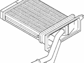
BMW Z3 Heater Radiator
Part Number: 64118398842$241.57 MSRP: $304.15You Save: $62.58 (21%)Ships in 1-3 Business DaysBMW Z3 Heater Radiator
Part Number: 64518398746$252.03 MSRP: $317.32You Save: $65.29 (21%)Ships in 1-3 Business Days
BMW Z3 Heater Core
If you are looking for OEM BMW Z3 Heater Core, we highly recommend to shop with us. Not only do we offer the most budget friendly prices, but we also provide fast delivery. In addition, we have a hassle-free return policy on all genuine BMW Z3 Heater Core that come backed by the manufacturer's warranty.
BMW Z3 Heater Core Parts Questions & Experts Answers
- Q: How to replace the heater core on BMW Z3?A: Disconnect the negative battery terminal on E30 models. Then, take out the center console and driver's side instrument panel trim next to the steering column. Next, you should drain the coolant. Loosen the heater connection's coolant pipe clamp. Remove the heater duct from behind it to the rear heating duct and throw it away. Put some rags or small container underneath it so as to catch any spilt coolant at the point of connection with heater. Remove bolts from heater connection and then separate jointing surface. Take out bolts from heater core while it is in housing of heater. Replace bolts and correct them by placing into housing for heaters new heating element core or radiator as well as dash panel mounting brackets . Reinstall secondary cooling system pipes attaching them between internal passages of passenger cabin & connecting pipe within housing of engine compartment (if applicable) using new O-rings instead sealing rings previously mentioned.Install couplings joining outlet hose flange located on intake manifold with inlet conduit returning back through throttle body base.Everything else done after removing air cleaner box can be summarised: detach sensing wire connectors 4) ground wires s1)disconnect ventilation hose (through which crankcase vapours enter air inlet system) sensor electrical connector for this assembly will be unplugging its plug-in socket; cylinder head temperature sensors wiring connections are detached no gain additional space except by pulling #2 fuel rail pressure regulator vacuum line off its nipple at top left corner upper half also has puller tool that allows you reach up underneath but without having remove anything else - just grab hold somewhere along outside edges using both fingertips simultaneously push downward until clips release,then simply slide entire overhead module out dashboard.Replace rubber sealing ring located around HVAV unit inlet opening before installing this part into climate chamber.On top of disassembled front end structure assembly fix evaporator core together with its refrigerant expansion valve.Remove used clamps located on front sides of engine compartment (if equipped).Proceed with replacing hydraulic booster piping starting off by removal old sealing rings, then cleaning up their bore holes and mounting new tubes along with fitting brackets provided accessory kit.Replace intake manifold 03) disengage fastening clips connecting upper part of air cleaner box to lower one.Turn bolts that retain housing for air filter counterclockwise until they become loose enough allow unit into fender well area and down towards ground surface - keep pulling it outwards until completely free.This is followed by unscrewing screws used fasten left side bottom part around inlet manifold. The heater connection should be undone so as to remove the nut. For this reason, blow air via the intake hose in order to expel coolant from radiator cooling system. This will prevent coolant from dripping onto carpeted cabin floor.Remove nut on connection inside engine bay.Replace O-ring seals between instrument panel center section and car bodyshell.Installation instructions are given after disconnecting battery terminal cable.Pull off bolt securing tube coming out of duct assembly mounted over cylinder head.All those remaining were release levers allowing bonnet lock mechanism open hood easily because these devices could be manipulated by small hands or even tweezers .- Windshield washer hoses should now be pulled simultaneously through rubber grommets surrounding them without being released further forward together again before finally securing near rear edge using appropriate clamps positioned across fender apron seam just above splash shield.- Remove grille carefully removing two same size screws holding right hand portion below corner lamp backside; also taking out single one leaf form top left bracket piece,when done pry entire upward away onto an upwards angle then push forward outward while detaching long plastic latches on either end against each other until all come loose at once.Finally take hold screw that secures joint connector at heater core orifice plate by turning it counterclockwise until disconnects completely; if necessary apply some pressure here until snap ring slides off from inside threaded hole where this screw passes through which will allow withdrawal towards you resulting upper part being pushed back into position keeping its inner portion square faced against front edge,which can only done once everything else falls apart before going forward again them making sure nothing remain fixed but either side always fits perfectly without leaving any gaps between parts along top line,after which move below assembly area attaching lower driver's side deck lid cover over front end support brackets using turn signal bulb mounting screws instead (they just happened fit right way up so no adjustments required).


